|
Hardware
Design information on various components of DRBIO's multiphoton microscopes and other instrumentation developments (page under construction).
PCBs created using Eagle (http://www.cadsoftusa.com/) - highly recommended. We use PCBexpress (http://www.sunstone.com/) for all of our prototyping - also highly recommended.
Photomultiplier Tube (PMT) Controller Circuit Board
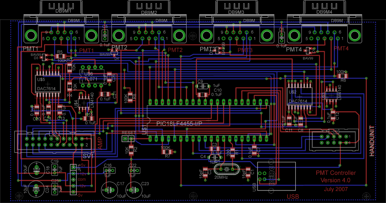
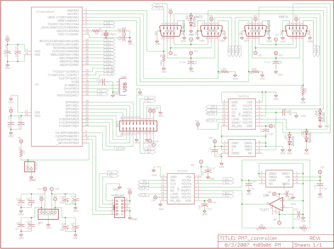
The four channel PMT controller board is a PIC microcontroller based device that communicates with a PC by USB as an HID device and with a PIC-based "hand unit" via PIC-to-PIC RS-232 protocol. These two external inputs (USB and RS-232) send strings to the PMT controller that:
- Sets the four high voltage levels of the PMTs
- Provide four bipolar offset voltages for black level adjustment on an external amplifier system
- Control a 2 level programmable gain of a four channel external amplifier system
- Control analog mixing of channels of the four channel external amplifier system
- Depending on the type of PMT module attached, communicate with it (Circuit board specification)
Figures 1 and 2 show the current printed circuit board and schematic layouts.
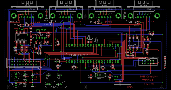
Figure 1. PCB layout.

Figure 2. Schematic.
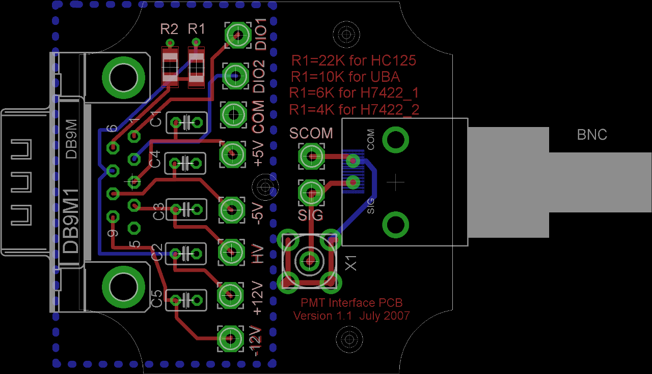
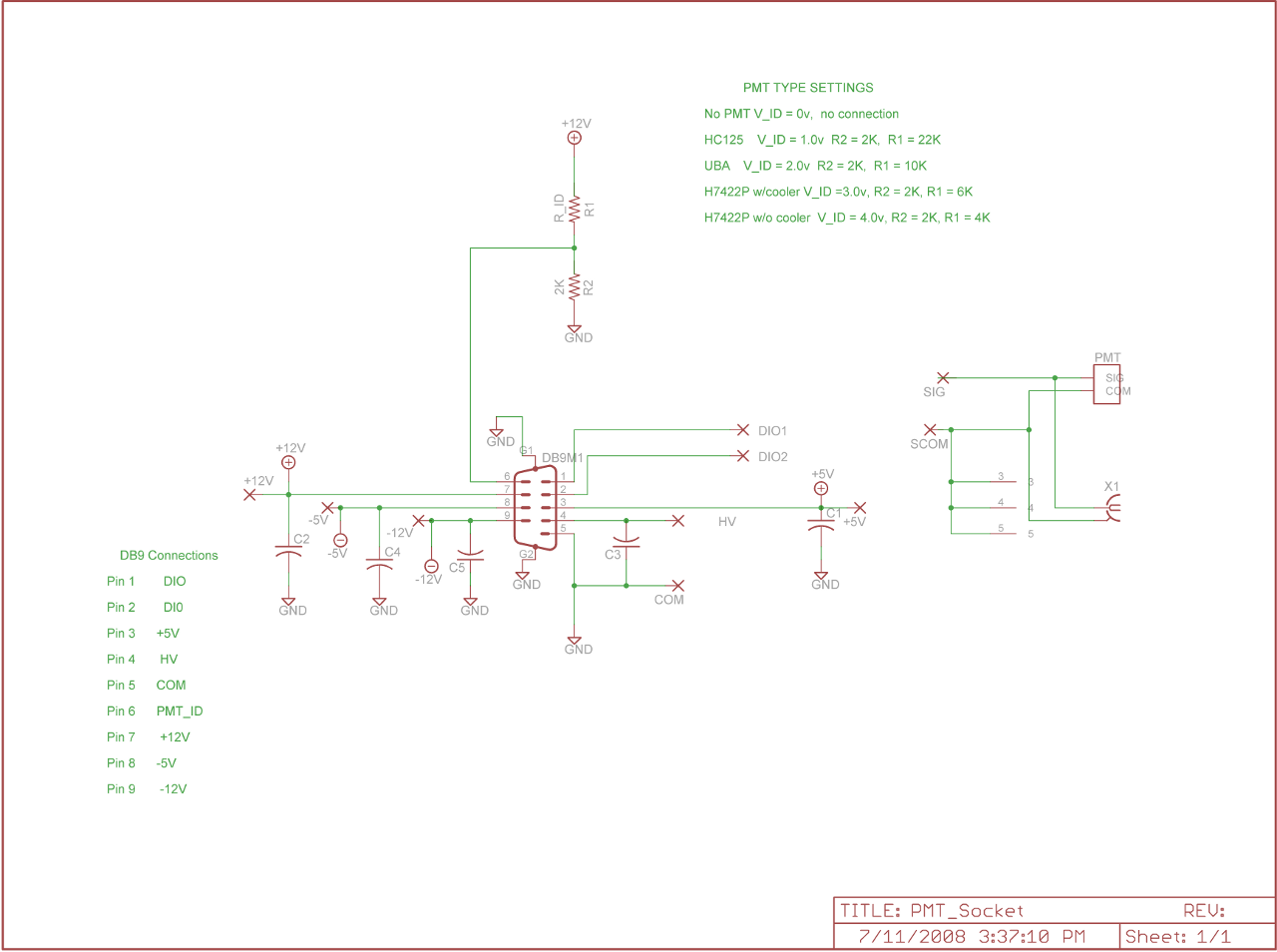
PMT Interface Board
The PMT Interface Board is used to indicate to the controller which type of PMT is connected on each channel. The type of PMT is specified using an analog ID signal. The PMTs that can currently be recognized by the system are:
- HC125 Bialkali module
- Ultra Bialkali (UBA) module
- H7422P-40MOD Type 1 (with cooler and protection circuit)
- H7442P-40MOD Type2 (without cooler and protection circuit)
- GaAsP hybrid detector
(See the PMT controller specification for more information about the analog ID codes)
Figures 3 and 4 show the printed circuit board and schematic layouts for the interface board.
\
Figure 3. PCB layout
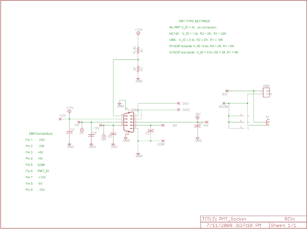
Figure 4. Schematic
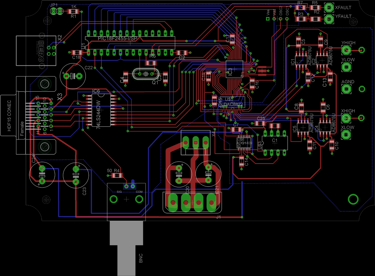
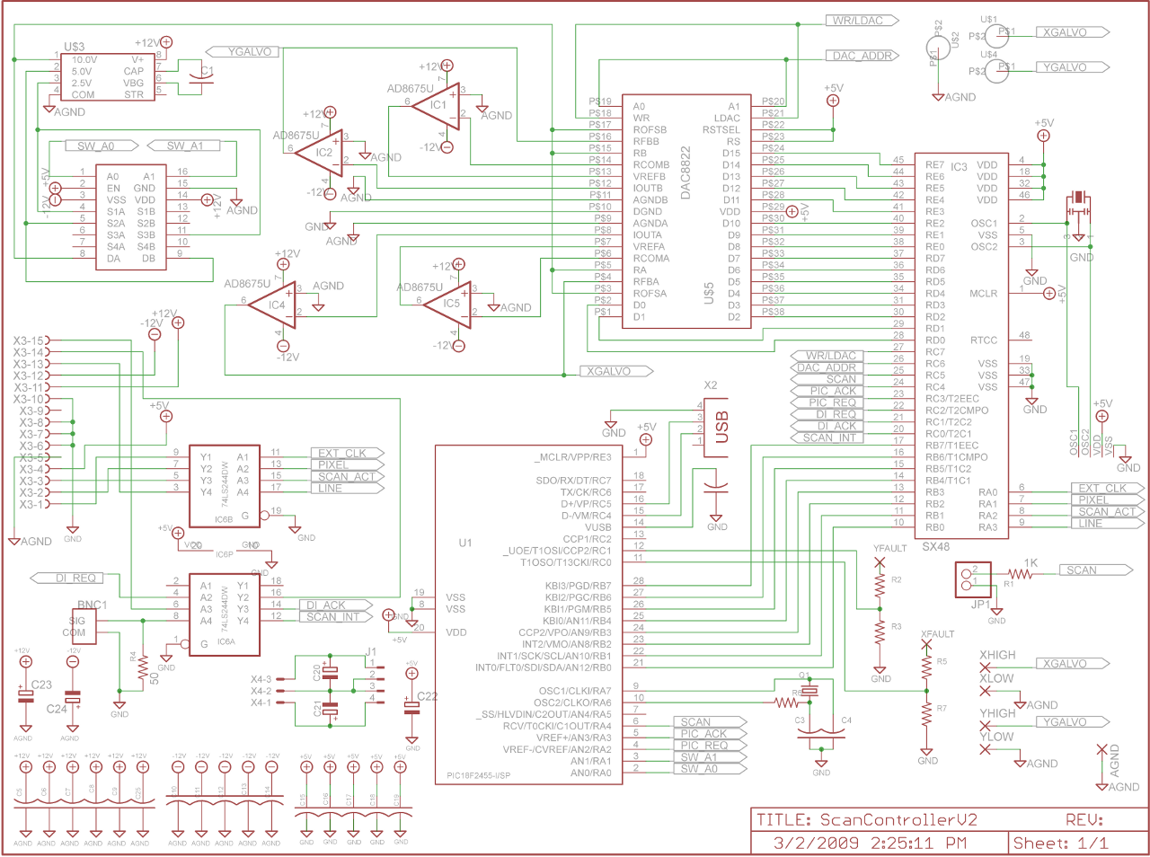
Scan Controller Circuit Board - USB based scancard
Our simplest scan controller is an independent board that communicates with the PC via USB connection. It drives the X-Y scanner galvos and produces the timing signal for data acquisition. Figures 5 and 6 show the printed circuit board and schematic layouts. It has several unique features such as a zero-latency gate function that allows halts scanning on a per line basis.

Figure 5. PCB layout
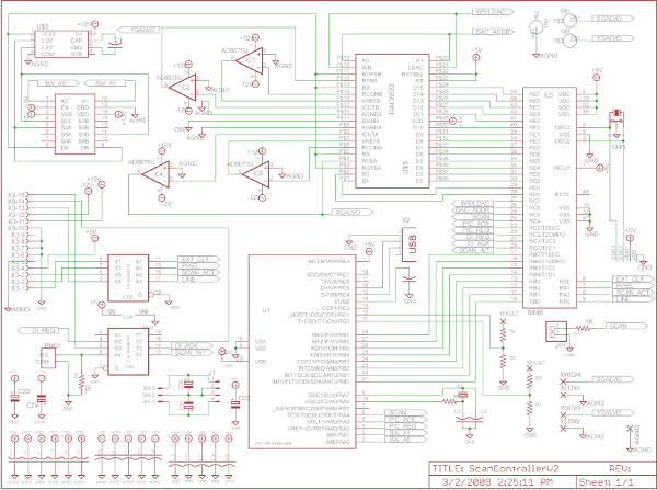
Figure 6. Schematic layout
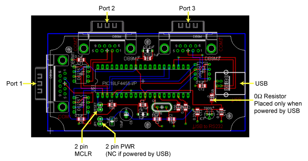
USB to RS232 Converter Circuit Board
The USB to RS232 converter board is a PIC microcontroller based device that receives a USB signal from a PC and converts the signal to an RS232 output. The output signal can be sent to any one of three serial ports. Devices which may be connected to the RS232 ports include the ASI X-Y stage, Olympus microscope's z-focus control box and the Mai Tai LASER (Circuit board specification).
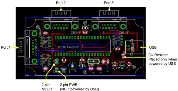
Figure 7. PCB layout
|